 GUANGZHOU HAOZHI INDUSTRIAL CO., LTD.
- Home
- About Us
-
Products
-
Machining center series
-
Engraving and Milling Spindle
-
Dental Milling Spindle
-
Rotary Table
-
Reducer
-
Core functional parts of the robot
-
PCB Spindle
-
Glass Grinding Spindle
-
Belt Driven and Direct Driven Spindle
-
Super Finish Spindle
-
Motorized spindle series for drilling and tapping center
-
Hydraulic static spindle series
-
Grinding Spindle
-
Lathe Spindle
-
Woodworking Spindle
-
Tool Holder
-
Collet
-
Linear motor series
-
Automated fixture (outside)
-
Automated fixture (inside)
-
Digital Controls
-
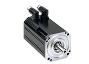
Servo Motor
-
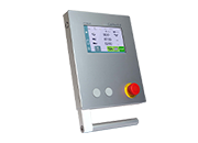
Bending machine control system
-
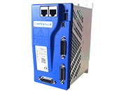
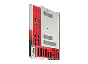
Servo Driver
-
Fuel cell compressor
-
- Service
- Investor Relations
- News
- Contact Us